The way Data Centers are operated is not too far off from how we set up corporate networking. Data Centers specialize in delivering content to the outside internet and internally. The way companies and regular people can have access to a data center can be done in multiple different ways. One may include renting racks from the data center itself. Another may be renting a server from the data center. Some will even self-host and have their own “data center”, although not as large as enterprise versions.
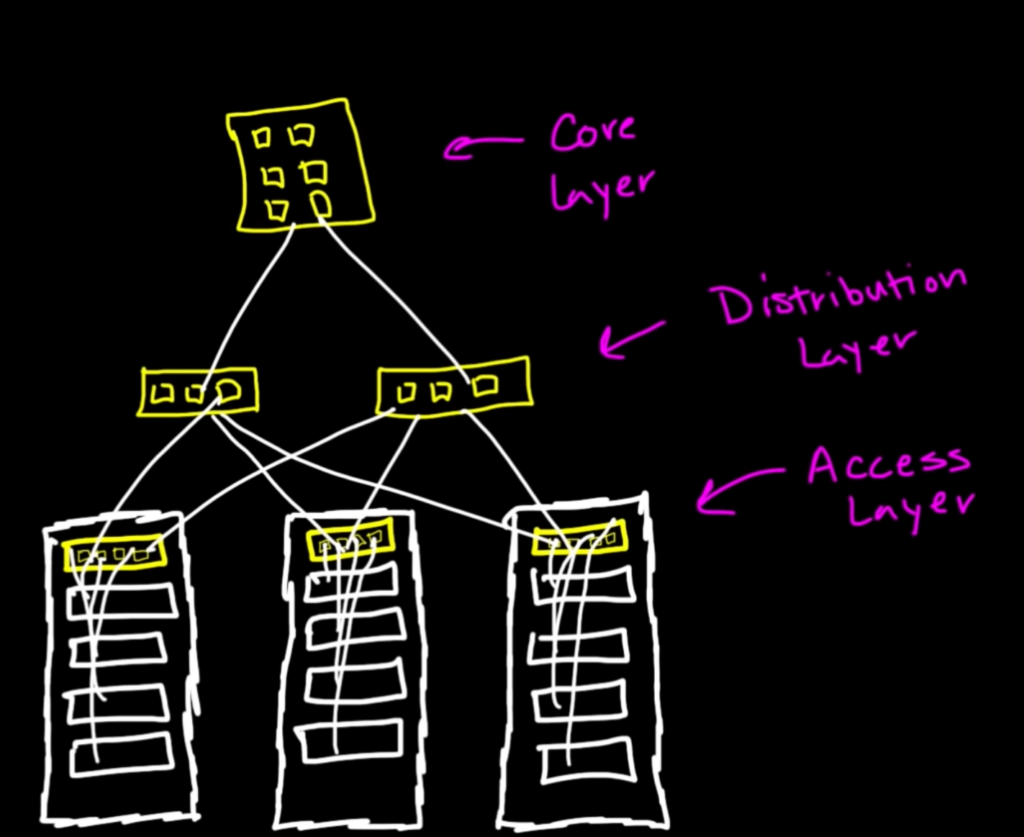
Below is how we used to operate commercial-size data centers. On each rack, there would be servers and above them would be the switches. These are called the TOR (Top Of Rack) switches and they are responsible for connecting the servers to the Distribution Layer switches. This next hop to the Distribution Layer would allow communication between racks and to the Core Layer which everything outbound and inbound come through.

The Access Layer and Distribution Layer can also be replicated, used to be commonly seen on larger scale data centers. The connection of clients coming through the internet to the servers through all the switches is what we call north-south traffic. Now this worked for a long period of time until the demand for low-latency communication between servers was needed for virtualization. This traffic is referred to as east-west traffic and it accounts for over 80% of traffic in data centers. The problem is now we designed our infrastructure to be optimized for north-south traffic and networking engineers came up with a solution to fit both forms of traffic.

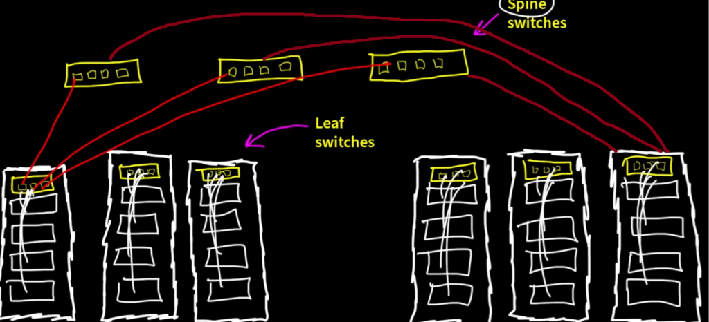
With a new design, we still keep our TOR switches, but they are now renamed to Leaf Switches. Next, we also keep our Distribution Layer switches and rename them to Spine Switches. Now, the connectivity changes quite a bit here. We are going to mesh all the leaf switches to the spine switches. What this means is that for every leaf switch, will have a connection to each spine switch. A picture below explains visually what it means to mesh all these together.
This design is what we call the Spine/Leaf or Clos design. This can get messy, but it’s worth the reward for lower latency between racks. The way the hops work is that let’s say one of the servers on the right wants to send/receive data from one of the servers on the left. The frame only has 2 hops, which is very low latency.
For the campus environment (for Cisgo equipment) we use the Catalyst switches. For data center applications we use Nexus switches. Another thing to note is that all switches in a data center use L3 switching (Multi-Layer Switch). This is great for not having to worry about a thing called “Spanning Tree” which is a loop prevention mechanism at Layer 2, which will be more understood later down the road. Because we are using layer 3 we can load balance connections and not have to worry about loops.
The diagram above can be seen as the Underlay design and there is another above that which is the Overlay design. The underlay design gets our servers connected, but the overlay design is where most of the automation with more advanced Cisco networking hardware is done.
