There are many different ways to design networks for many other applications. In this section, we will go over some good ways to set up networks for enterprise applications and for small businesses.
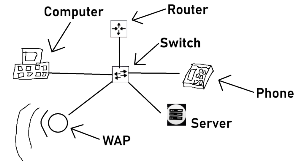
Firstly we will actually start with an example of a type of network you should NOT apply out in the field for the commercial/enterprise campuses. As shown below, you do not want to set up a traditional SOHO (Small Office Home Office) network layout for these types of applications. This is mainly done for redundancy. You want to make sure as many things as possible are still reachable when any hardware breaks. Now for a simple small business that doesn’t need the extra hardware, this layout works perfectly, and the same may also go for your at-home network.

Now here is where one of these simple networks could run into problems. Let’s say you wanted to expand your infracture and you add another switch to the first switch. Daisy chaining switches is generally not a great idea. It works, but it’s not practical especially depending on how and where these links between switches are. Imagine one connection; let’s say from the switch to the second switch breaks. You will lose that link all the way down the chain. Maybe the first switch goes down, or the link between the router in the switch breaks. You can see that it’s not an ideal solution to the expansion of devices. Now sure, multiple connections from each switch and the router do help, but that still does not solve the hardware itself breaking and causing an outage.
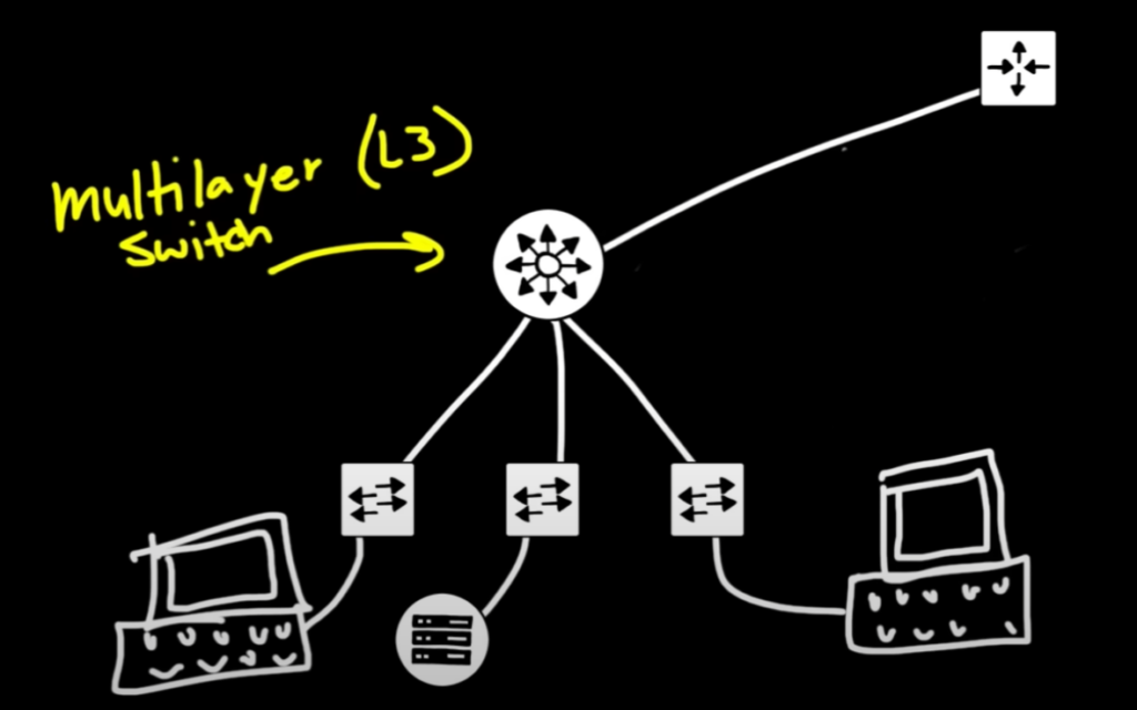
To help solve this issue of more devices connected and wanting high redundancy you could have every switch connected to the router. But the router isn’t just helping devices on your network reach the internet, which it’s great at doing, but keep in mind they may also be talking to each other which is great for what a switch does. Now we learn about something that does great at both Layer 2 and Layer 3 communication. Meet the Multilayer Switch, often referred to in the networking world as a Layer 3 Switch. It does exactly what it says it is and they are very good at what they do. An example of what a better network looks like with a Multilayer Switch can be shown below.

Now we can see another single point of failure from the MLS to the router and we will discuss how we can fix that. Keep in mind that as you connect more devices and add more infrastructure (ie. cables, hardware) the bill can go exponentially up.
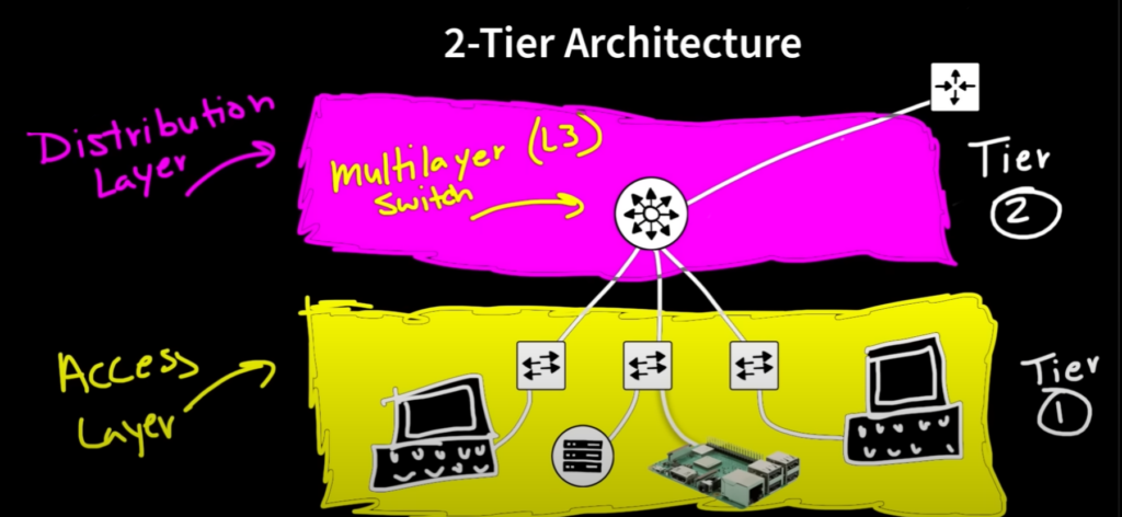
We can now label what these types of networks are called. The one shown above can be seen as a type of 2-tier architecture. This is where we divide up the different layers of how things are connected. Shown below is a picture of the types of layers and what each does. Our first layer, the Access Layer is responsible for giving clients connectivity to other machines and the internet. These are typically connected to a lower-powered switch. Then the next layer, the Distribution Layer. This layer is responsible for distributing those packets/frames throughout the whole network.

The hardware needed for the distribution layer can be quite expensive and large. They also operate at unbelievable data rates. Shown below some of Cisgo’s distribution layer-worthy switches. Some examples may include the Catalyst 9600. It can handle a peak of 25.6 Tbps throughput which is an absolutely insanely fast data rate. Listed next to it is another Cisco switch; the Catalyst 9300L. Again, blazing fast 320 Gbps for maybe a good applicant for those “lower” traffic situations. Cisco has a very good reputation for their networking hardware reliability and high uptime percentage.


A post from Bosons courseware regarding the Distribution Layer in a bit more detail.
“The distribution layer aggregates uplinks from access layer devices and provides services to both the access
boson switch curriculum ed.300-115 © 2017
layer and the core layer. Positioned between the access and core layers, the distribution layer is the ideal
place to perform functions such as QoS resource reservation, interVLAN routing, packet manipulation, and
route summarization. In addition, access control lists (ACLs) can be used in the distribution layer to enforce
organizational security policies and to filter the flow of traffic between the access and core layers.”
Diving into more redundancy we could double up connections coming from the router to the L3 Switch and to all the other Access Layer switches. On top of this, include an additional L3 switch and double that connection up to. Now we have a lighter load on our Distribution Layer hardware and every connection in both our tiers does not contain a single point of failure; which is great. Even some will go as far as to implement another router for even more redundancy. Remember that most of this is ideal, but not necessarily done practically unless whoever wants this architecture has the money and resources to put towards it; because it can get very expensive very quickly.
Imagine now we are dealing with a serious system. A system where 3 or more of these 2-tier architecture systems are put into place onto multiple campuses. Now we have a problem when it comes to redundancy. Way too many connections as it is are already in place. Now adding dual copper connection links between multiple campuses can get a bit hectic. This is where we need 3-tier architecture. The way this works can be visualized below. We have added a new layer called the Core Layer. The purpose of this layer is exactly what it says it is; the core. This is responsible for the centralization of multiple locations/campuses. This is where you would put the serious L3 switches. You can think of this as the new Distribution Layer.
“The core layer provides a high-speed backbone that interconnects distribution layer devices. The core layer
BOSON SWITCH CURRICULUM ED.300-115 © 2017
should be optimized to minimize the latency through the backbone; thus very little packet manipulation and
route processing should occur in the core layer. The core layer is dependent on the distribution layer to enforce
security and QoS policies and to perform packet manipulation and route optimization”
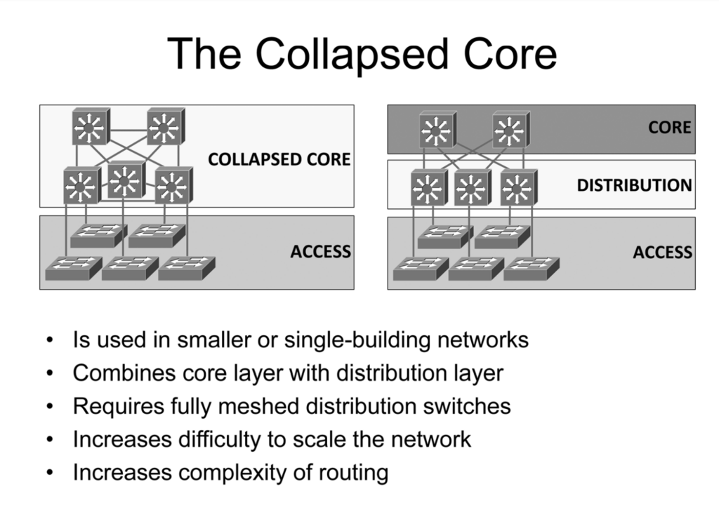
As you would think though, the Core Layer seems very similar to the Distribution Layer and you would be right. They actually call the Distribution Layer the Collapsed Core layer because they are so similar; it really just depends on your physical layout where to choose between a 2 or 3-tier architecture.
“When the distribution layer contains a small number of switches or resides in a single building, a physically
BOSON SWITCH CURRICULUM ED.300-115 © 2017
distinct core layer may not be necessary. In this case, the functionality of the core and distribution layers can be
combined. However, it becomes necessary for the distribution layer switches to maintain a full-mesh topology
to ensure that a link or device failure will not isolate part of the network.”

